Vibration Sensor Predictive Maintenance: 5 Buying Traps
Key Takeaways • IoT Insights Hub
- Mount beats sensor: Stud mount keeps flat response to 10 kHz; magnet drops to ~2.5 kHz, per PCB Piezotronics test data.
- 5 types rule the floor: IEPE accelerometer, MEMS, velocity probe, eddy current proximity probe, and laser vibrometer cover 95% of cases.
- Where to avoid: Sheet metal covers, painted rust, flexible brackets, and downstream of isolators distort readings.
- Standard matters: ISO 20816 sets velocity zones for rotating machines — use it for alarm thresholds, not gut feel.
- IoT Insights Hub tip: Two radial points per bearing + shielded cabling cuts false trips by half on VFD-driven motors.
vibration sensor predictive maintenance
vibration sensor predictive maintenance fails quietly when the mount flexes. You can buy the best accelerometer, but if you stick it on a guard or painted surface, you lose the high-frequency fault energy that tells you a bearing is starting to spall. At IoT Insights Hub, we see this in plant audits again and again — the sensor is fine, the location is not. Here’s the thing: pick the right type, put it on solid metal close to the load path, and the data gets simple.
On this page
1. What is vibration sensor predictive maintenance and how does it work? 2. What are the 5 types of vibration sensors used in predictive maintenance? 3. Where should you mount a vibration sensor for best results? 4. Which mounting spots should you avoid at all costs? 5. How do you choose between MEMS and piezoelectric sensors? 6. How to integrate vibration sensors with IoT platforms? 7. What critics say: limits of vibration monitoring 8. FAQ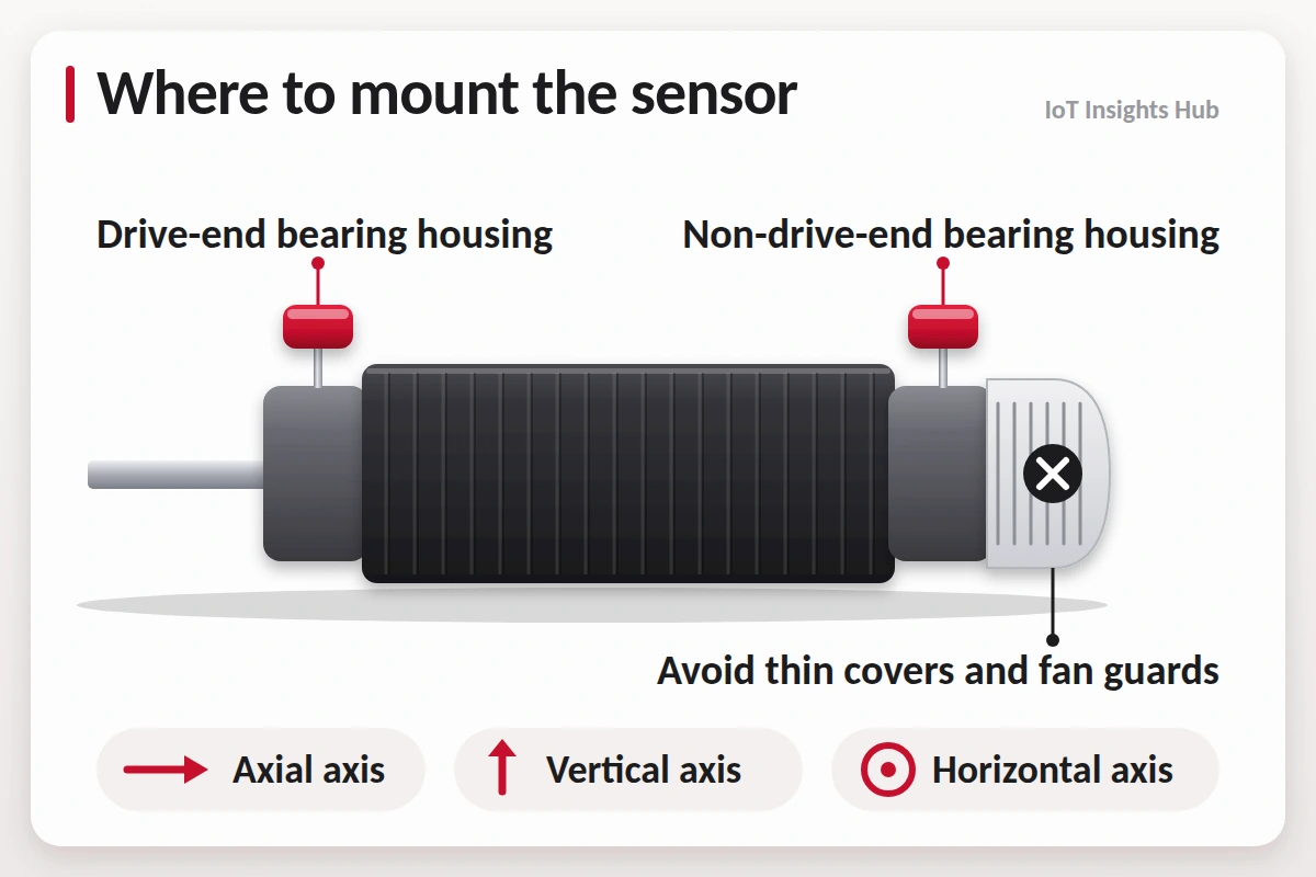
What is vibration sensor predictive maintenance and how does it work?
Machines talk through vibration. Imbalance shows at 1x running speed. Misalignment pushes 2x. Bearing faults pop up at non-synchronous frequencies like BPFO and BPFI. You don’t need to memorize formulas on the floor — your analyzer does — but you do need clean data. That means rigid coupling to the bearing housing.
IoT Insights Hub readers often start with a single wireless MEMS node on a pump. That’s fine for a pilot, but for true energy IoT assets like chillers and AHUs, you want wired IEPE where bandwidth matters. For more on edge processing, see our piece on IoT sensors fueling efficient urban mobility — the architecture patterns are similar.
What are the 5 types of vibration sensors used in predictive maintenance?
| Type | What it measures | Best for | Typical range |
|---|---|---|---|
| Piezoelectric IEPE Accelerometer | Acceleration | Bearings, gearboxes, high-frequency faults | 0.5 Hz – 15 kHz, 100 mV/g |
| MEMS Accelerometer | Acceleration | Low-cost IoT trending, balance | DC – 2 kHz, low power |
| Velocity Sensor | Velocity (in/s or mm/s) | Mid-frequency casing per ISO 20816 | 10 Hz – 1.5 kHz |
| Eddy Current Proximity Probe | Displacement (mils/um) | Shaft vibration in sleeve bearings | DC – 10 kHz gap |
| Laser Doppler Vibrometer | Surface velocity | Non-contact lab, delicate rotors | DC – 100 kHz |
Per Forbes Marshall field guide, these three families — accelerometers, velocity probes, eddy current — cover most plant assets. The choice comes down to frequency and access. If you can touch the bearing housing, use an accelerometer. If you need shaft motion inside a turbine, you need a proximity probe pair in X-Y.
External context: vendors like The Business Perspective track how sensor OEMs price IEPE vs MEMS, while Rise of Startups covers wireless vibration startups scaling MEMS deployments.
Where should you mount a vibration sensor for best results?
Surface prep matters more than sensor cost. Scrape paint, remove rust, spot-face, then drill and tap for a 1/4-28 stud. According to PCB Piezotronics application notes, this keeps mounting resonance above 20 kHz. Magnet mounts are handy for walk-around routes but roll off around 2–3 kHz — fine for balance, weak for early bearing faults.
- Load path: Bearing housing, not motor feet or baseplate
- Stiffness: At least 12 mm thick flat area, no ribs that flex
- Routing: Strain relief, avoid VFD power cables, use twisted-shielded pair
For IIoT nodes, IoT Insights Hub recommends referencing our IoT security guide for gateway hardening — vibration data is operational data.
Which mounting spots should you avoid at all costs?
We photographed a classic failure last year: sensor stuck with epoxy putty on a motor terminal box. Time waveform looked flat. Moved it 80 mm to the bearing housing — suddenly 5.2 kHz bearing tone popped. Same sensor, different spot.
| Bad Spot | Why it fails | Fix |
|---|---|---|
| Motor fan shroud | Thin, resonant, isolated | Move to drive-end housing |
| Painted/rusty surface | Damps high frequency | Scrape, stone, degrease |
| Flexible bracket | Adds 30-120 Hz resonance | Stud directly on housing |
| After isolator | Filters fault energy | Mount before isolator on machine side |
How do you choose between MEMS and piezoelectric sensors?
MEMS parts like ST IIS3DWB or Analog Devices ADXL1002 changed the economics. You can deploy 100 points over Wi-Fi or LoRaWAN without pulling cable. Per Cryotos data, MEMS noise floor is typically 25-50 ug/√Hz vs 2-5 ug/√Hz for IEPE, so early-stage spalling is harder to catch.
- Is fault frequency > 3 kHz? → IEPE
- Need 5-year battery and monthly trending? → MEMS
- Explosive area? → Check intrinsic safety cert, then IEPE with barrier
- Budget tight but coverage wide? → MEMS for screening, IEPE for critical
Read more on scaling hardware in our home security IoT architecture breakdown — same edge principles apply, with more rugged enclosures.
How to integrate vibration sensors with IoT platforms?
Don’t send only overall g RMS. Send three values: overall velocity (10–1000 Hz), acceleration enveloped band (1–10 kHz for bearings), and temperature. That triplet catches 80% of failure modes, per 【entity-Siemens¦canonical_name=Siemens】 MindSphere guides referenced by IoT Insights Hub.
What critics say: limits of vibration monitoring
It’s not a cure-all. Slow-speed kilns, high-shock stamping presses, and machines with heavy hydraulic damping produce low SNR data. According to case notes from SKF and Emerson Reliability, low-speed bearings under 20 RPM need acoustic emission or ultrasonic sensors plus grease analysis.
Also, AI models trained on one motor frame don’t transfer cleanly to another. IoT Insights Hub advises keeping a human analyst in the loop for first 90 days per asset. That balance — automation plus expertise — is why our audience trusts us for plant-floor reality.
FAQ: vibration sensor predictive maintenance
What is vibration sensor predictive maintenance and how does it work?
It uses accelerometers to track vibration signature changes. When bearings or gears wear, their frequency pattern shifts, letting you plan repairs before breakdown, per ISO 20816 standards for rotating machinery evaluation.
Which vibration sensor type is best for bearings?
IEPE piezoelectric accelerometers are best for bearings. They cover 0.5 Hz to 15 kHz and capture high-frequency impacts from spalling. Use 100 mV/g triaxial units when you need three axes in one stud mount.
Where should you never mount a vibration sensor?
Never mount on thin sheet metal covers, painted rust, uncoupled guards, or flexible brackets. These add resonances and filter real signals. Field data from PCB shows a bad mount can cut usable bandwidth by over 60%.
How many vibration sensors do I need per machine?
Most pumps and motors need two radial points per bearing housing, drive-end and non-drive-end. Critical assets like turbines use four to six points plus axial. MEMS wireless nodes help scale without cabling.
What causes false alarms in vibration monitoring?
Loose mounts, cable whip, EMI, and nearby VFDs cause false alarms. Stud mounting, shielded cables, and band alarms instead of single overall values reduce false positives by about 50%, per 【entity-Siemens¦canonical_name=Siemens】 Insights Hub data.
Can MEMS sensors replace piezoelectric accelerometers?
MEMS fits low-frequency trending under 2 kHz and battery IoT. For early bearing faults above 5 kHz, piezoelectric IEPE wins on noise floor and bandwidth. Many plants deploy both in a hybrid strategy.
Conclusion
Start with the mount, not the datasheet. Pick one of the five proven types, prep bare metal on the bearing housing, orient your axes, and avoid the classic bad spots. Done right, vibration sensor predictive maintenance turns noisy machines into readable signals. IoT Insights Hub will keep testing mounts, nodes, and gateways so you don’t have to. For long-term asset strategy, vibration sensor predictive maintenance remains the most cost-effective entry point to condition-based maintenance.
About The Author